Airfoils & Angle of Attack
Before lift, drag, dissymmetry, or stall, there's the airfoil — a cross-section of a wing or rotor blade with shape and orientation chosen to extract useful force from moving air. Every aerodynamic concept in helicopter flying assumes you already know the vocabulary: chord, camber, angle of attack, angle of incidence, relative wind. This page lays out those terms, the difference between symmetrical and cambered airfoils, and how the airflow over an airfoil produces lift in the first place.
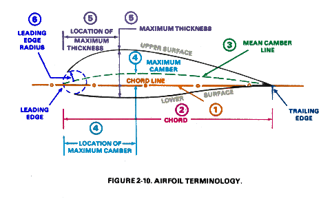
The vocabulary
- Chord line — a straight line from the leading edge to the trailing edge. The reference axis for measuring angle of attack and angle of incidence.
- Mean camber line — a curve drawn through points equidistant from the upper and lower surfaces. On a symmetrical airfoil the mean camber line is identical to the chord line; on a cambered airfoil it curves upward.
- Leading edge / trailing edge — the front and rear of the airfoil. On rotor blades the leading edge takes the brunt of erosion, bird strikes, and ice; pre-flight always includes a close look at it.
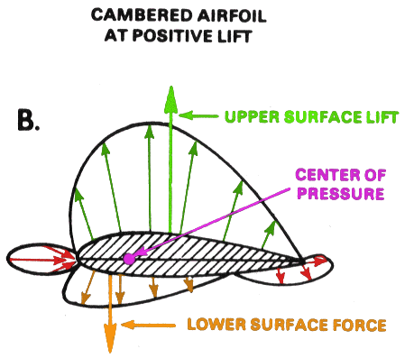
- Upper / lower surface — for an airfoil at a positive angle of attack producing lift, pressure on the upper surface is lower than ambient and pressure on the lower surface is higher than ambient. The differential is what we call lift.
- Maximum camber — the largest displacement of the mean camber line from the chord. Higher camber = more lift at any given AOA, at the cost of more drag.
- Thickness — the maximum distance between upper and lower surfaces. Modern rotor blades use thin airfoils to delay shock formation at the high tip speeds of forward flight.
Symmetrical vs cambered airfoils
Two families of airfoil are used on helicopter rotor blades, and the choice has operational consequences.
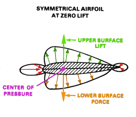
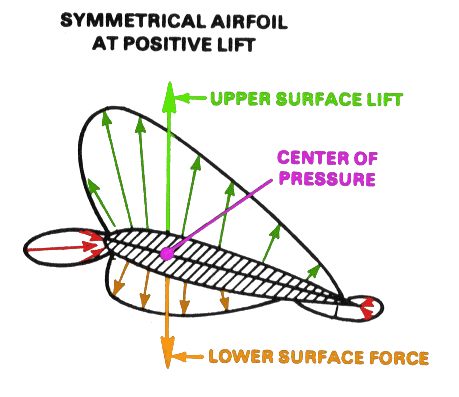
Symmetrical airfoils have identical upper and lower surfaces. The mean camber line lies along the chord. A symmetrical airfoil produces zero lift at zero angle of attack — the upper and lower flow patterns cancel. Many older rotor blades (Robinson R22/R44, Bell 47, Bell 206 main rotor) use symmetrical airfoils because they have a stable, predictable center-of-pressure location that doesn't shift much with AOA. Stable center of pressure = less pitching moment fed into the control system = simpler rotor.
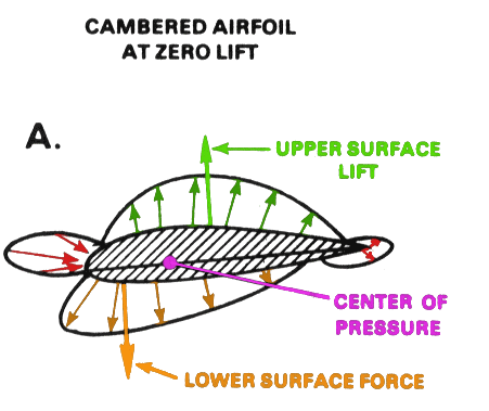
Cambered airfoils have an upper surface that curves more than the lower surface — the mean camber line is bent upward. A cambered airfoil produces positive lift even at zero AOA, because the air is already forced to take a longer path over the upper surface. Cambered blades are common on newer / higher-performance designs. They produce more lift per unit chord, allow lower blade pitch for the same lift, and have a more efficient lift-to-drag ratio at moderate AOA — at the cost of a center of pressure that shifts with AOA and a higher pitching moment.
Angle of attack vs angle of incidence
Both angles are critical, both are commonly confused, and the difference comes up on every oral exam.
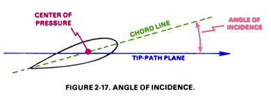
- Angle of incidence is mechanical. It's the pitch angle the swashplate dialled into the blade. It doesn't change with airspeed, RPM, or flight regime — only when you move cyclic or collective.
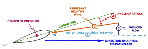
- Angle of attack is aerodynamic. It's the angle between the chord and the air the blade is actually meeting. It changes constantly as the blade flaps, as the helicopter accelerates, as wind shifts, as you change collective.
You set angle of incidence. The air determines angle of attack. AOA is the one that produces lift and (above the critical AOA) stalls the airfoil. The whole point of blade flapping is to equalize AOA across the disc when the cockpit can only adjust AOI.
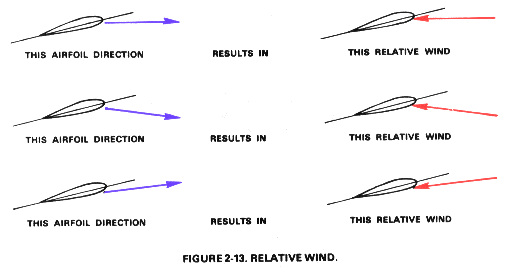
Relative wind
Relative wind is the airflow the airfoil actually meets. It's parallel and opposite to the airfoil's path through the air. If you're flying straight ahead at 100 knots, the relative wind is straight at you at 100 knots. If you're hovering, the relative wind is whatever the air around you is doing — usually mostly induced flow coming down through the disc.
On a rotor, every blade meets a different relative wind at every azimuth position. The components of that relative wind matter:
- Rotational component — the blade's own motion through the air, due to rotor RPM. Largest at the tip, zero at the hub.
- Translational component — the helicopter's forward (or sideways) motion through the air.
- Induced (vertical) component — the downward flow through the disc caused by the rotor's own lift production. Higher in a hover, lower in fast forward flight.
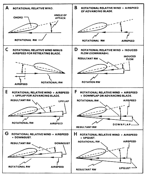
The blade always sees the vector sum of all three components. Change any one — increase RPM, accelerate forward, pull collective — and the relative wind direction shifts. The angle of attack shifts with it, even if you didn't touch the cyclic or change blade pitch (AOI).
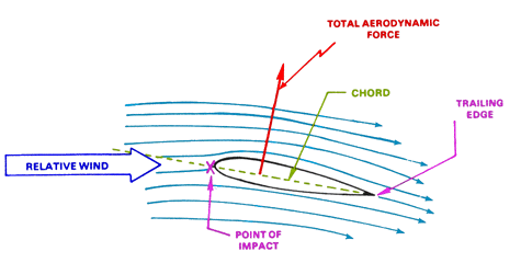
How an airfoil produces lift
The shortest honest answer: an airfoil at positive AOA deflects air downward, and by Newton's third law that produces an upward force on the airfoil. The longer answer involves pressure distribution, but the deflection picture is the one that matters for understanding what happens when AOA changes.
Two consequences worth holding in mind:
- More AOA → more deflection → more lift, up to the critical AOA. Past the critical angle, flow on the upper surface separates and the airfoil stalls. Lift collapses, drag spikes.
- Lift acts perpendicular to the relative wind, not perpendicular to the chord line. This matters when the airfoil is operating in an unusual flow direction — like the descending air of vortex ring state, or the upward-flowing air through an autorotating rotor.
Forces on the airfoil
Wind on an airfoil produces a total aerodynamic force. We decompose that force into two components by convention:
- Lift — perpendicular to the relative wind. The useful component for sustaining flight.
- Drag — parallel to the relative wind (opposing the airfoil's motion). The penalty for producing lift.
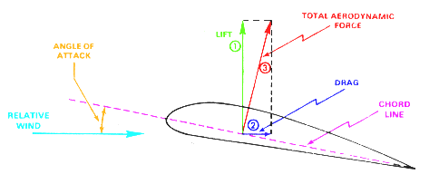
The lift-to-drag ratio (L/D) is the efficiency metric. High L/D = lots of lift for a little drag, which is what you want at every flight regime. Rotor blade design is a constant trade-off between maximizing L/D at the operational AOA range and keeping the airfoil well-behaved (stable center of pressure, gentle stall, low pitching moment) across the operating envelope.