Rotor System
The main rotor is the helicopter's primary lift-generating surface — and unlike a fixed wing, it has to handle the asymmetric airflow of forward flight by allowing each blade to move independently in three directions. The way the rotor system permits (or prevents) those movements defines the system type. Three main families: fully articulated, semi-rigid (teetering), and rigid. Each has distinct operational characteristics.
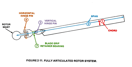
Fully Articulated
Each blade is mounted on hinges that permit three independent motions:
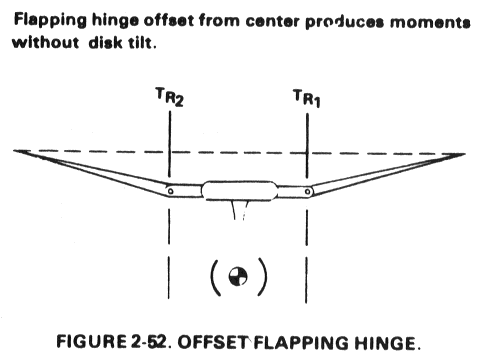
- Flap — vertical motion. Solves dissymmetry of lift by letting each blade rise and fall through the rotation cycle.
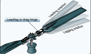
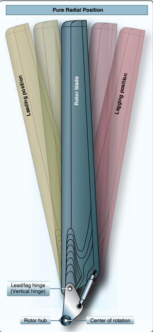
- Lead-lag — forward-aft motion in the plane of rotation. Compensates for blade-flapping-induced velocity changes via conservation of angular momentum.
- Feather — rotation about the blade's spanwise axis. This is the pitch change you command with cyclic and collective.
Used on most multi-blade systems with 3+ blades: Bell 206/407, Sikorsky family, most turbine helicopters.
Strengths: smooth in flight (vibration is absorbed by hinge motion), handles dissymmetry of lift well, allows higher airspeeds.
Weaknesses: more complex, more parts, more maintenance. Lead-lag freedom requires drag dampers — and dampers are themselves a failure mode that can cause ground resonance.
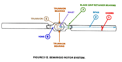
Semi-Rigid (Teetering)
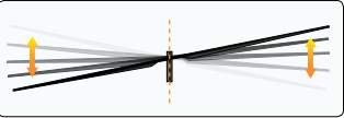
Two blades fixed to a common hub that can teeter as a rigid unit on a single hinge. The blades cannot lead-lag independently — they're rigidly connected at the hub. Flapping happens collectively (one blade up, the other down by the same amount) rather than individually.
Used on most two-blade systems: Robinson R22/R44, Bell 47, Bell 206 (for the main rotor — actually a hybrid).
Strengths: simple, lightweight, fewer parts, less maintenance. Immune to ground resonance because there's no independent lead-lag motion.
Weaknesses: Susceptible to mast bumping in low-G situations — the rotor can teeter past its mechanical stop and contact the mast, which has caused several fatal accidents in Robinsons. Also produces a 2-per-rev vibration that's hard to damp out.
Rigid
Blades attached to the hub with no flapping or lead-lag hinges. Forces from dissymmetry of lift are absorbed by blade flexibility (the blades themselves bend) rather than hinge motion. Feathering is still permitted (you still need pitch control).
Used on some advanced designs: BO-105, Lynx, some MD and Eurocopter variants.
Strengths: Crisp control response, capable of negative-G maneuvering (no mast bumping risk because nothing teeters). Used in military and some EMS aircraft for demanding operational profiles.
Weaknesses: Higher airframe stress (the bending forces from dissymmetry are fed into the airframe rather than absorbed by hinges). More expensive blades. Generally heavier overall structure.
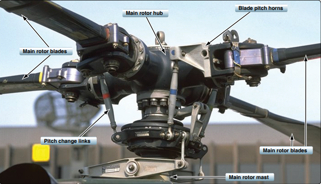
Pitch control: the swashplate
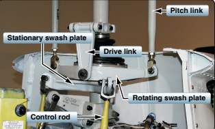
However the blades attach to the hub, every rotor system needs a way to change blade pitch while the rotor is spinning. That job belongs to the swashplate — a pair of plates stacked on the rotor mast that translate stationary cockpit inputs into rotating-frame pitch commands.
- Stationary (lower) swashplate — moves up and down with collective input and tilts in any direction with cyclic input, but does not rotate with the rotor. The cyclic and collective servos push on this plate.
- Rotating (upper) swashplate — bolted to the stationary plate through a bearing, it follows the stationary plate's motion but also rotates with the rotor. Pitch-change links from each blade connect to this plate.
Move the stationary plate up → both plates rise → every blade gets more pitch (collective). Tilt the stationary plate forward → both plates tilt forward → each blade gets cyclic pitch change once per revolution. Gyroscopic precession is mechanically pre-corrected by where the pitch-change links attach, so cyclic forward yields disc tilt forward, not 90° off.
How rotor type affects you as a pilot
- Fully articulated — pre-flight checks include drag dampers and individual blade attachments. Watch for ground resonance on touchdown.
- Semi-rigid — never push cyclic forward in low-G situations. Mast bumping is the failure mode.
- Rigid — handles aggressive maneuvering, but fatigue limits matter. Watch flight cycle counts on critical components.
If you're transitioning between aircraft, verify which rotor type the new aircraft uses. Recovery techniques and operational limits change.