Autorotation Aerodynamics
Autorotation is the unpowered descent that keeps the rotor spinning — and the helicopter survivable — after a loss of engine power. The aerodynamic mystery is that the rotor keeps turning at flight RPM even though no engine is driving it. The answer lies in how upward airflow through the descending disc divides the blade into driving, driven, and stall regions, with the driving region producing enough rotational force to spin the rotor against the drag of the other two. This page covers the steady-state aerodynamics; the maneuver itself is on the PPL Maneuvers page.
Also called: auto, power-off descent, engine-out
Why the rotor keeps turning
In normal flight the engine drives the rotor through the transmission. The rotor's blade pitch produces lift (good) and drag (the cost). The engine supplies the energy to overcome that drag.
When the engine quits, the freewheeling unit disengages the rotor from the dead engine — otherwise the rotor would be trying to spin the engine, and the engine's friction would drag rotor RPM down quickly. Now the rotor is on its own.
The pilot's first action is to lower collective. This drops blade pitch (AOI) sharply, which reduces the AOA across most of the disc and the drag on the rotor. The helicopter begins to descend.
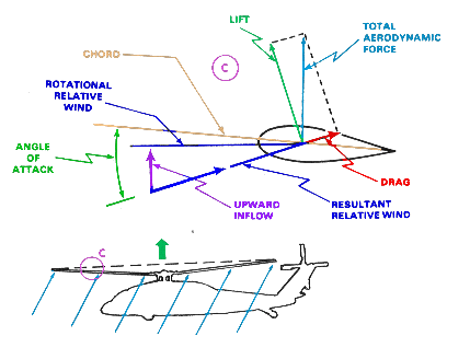
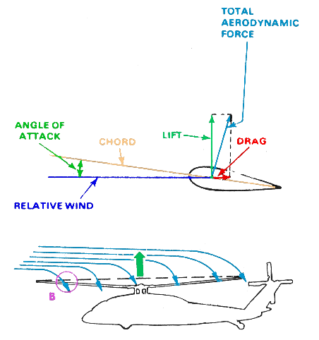
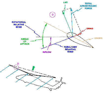
As descent rate builds, air starts flowing upward through the disc. This upward flow tilts the relative wind upward, which tilts the total aerodynamic force vector forward of the rotor's vertical axis on a portion of each blade. That forward-leaning force has a component along the direction of rotation — it accelerates the blade tangentially, replacing what the engine used to provide. The rotor "drives itself" off the upward airflow.
The three regions of an autorotating blade
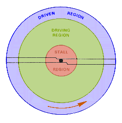
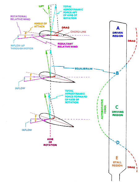
The forward-tilting of the relative wind isn't uniform across the blade. Near the root, the rotational speed of the blade is low and the upward flow dominates; near the tip, the rotational speed is high and the upward flow makes a smaller angle. Three distinct regions form along the span:
- Driven region (outer ~25–30% of the blade) — high rotational speed means upward flow tilts the relative wind only slightly. The total force still tilts aft of the rotational axis. The blade is producing useful lift, but this region is a net drag — it consumes rotor RPM rather than producing it.
- Driving region (middle ~50% of the blade) — moderate rotational speed and significant upward flow tilt the relative wind enough that the total force tilts forward of the rotational axis. This region produces tangential force that spins the rotor. It's where the auto comes from.
- Stall region (inner ~25% of the blade) — rotational speed is low and the relative wind angle is so steep that AOA exceeds the critical angle. The blade is stalled here. No useful lift, large drag — this region consumes RPM and energy.
The rotor reaches steady-state RPM when the driving region produces exactly enough tangential force to overcome the drag of the driven and stall regions. Higher descent rate moves the boundaries — more driving region, less driven region — and the rotor speeds up. If RPM drifts above the green arc, the pilot raises collective slightly to add drag and slow the disc back down.
Autorotation in forward flight
Add forward airspeed and the picture changes — the rotor now has advancing and retreating sides on top of the radial driving/driven/stall structure. The regions are no longer concentric rings; they distort around the disc, growing on one side and shrinking on the other depending on how the rotational and translational components combine.
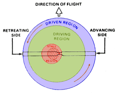
This is why autorotations are easier with some forward airspeed: more of the disc is in the driving region, RPM is more stable, and the helicopter has airspeed available to flare. Vertical autorotations (no forward airspeed) put the entire disc in the concentric pattern with a large stall region and small driving region — RPM management is harder, descent rate is higher, and the flare has nothing to work with.
Best autorotation airspeed varies by helicopter (R22: ~65 kt, R44: ~70 kt, Cabri G2: ~60 kt). The POH publishes both a max-glide airspeed and a min-descent-rate airspeed; they aren't quite the same number.
What changes after power loss — force vectors in transition
The aerodynamics of autorotation aren't static — they evolve through three phases after power loss.
- Phase 1 — Entry. Engine quits. Pilot lowers collective immediately. Rotor RPM drops momentarily as the previously powered drag is suddenly unopposed, but the reduced blade pitch limits the drop. Descent rate begins to build.
- Phase 2 — Steady-state. Upward flow stabilizes. The driving region produces enough tangential force to maintain rotor RPM. The helicopter descends at a stable rate, with RPM controlled by small collective adjustments.
- Phase 3 — Flare and touchdown. See the next section.
Autorotative deceleration — the flare
Near the ground, the pilot pulls aft cyclic and the helicopter "flares." The disc tilts back relative to the descent path; the rotor scoops air and decelerates the helicopter both vertically and horizontally. Simultaneously, the increased AOA across the disc increases rotor RPM — the flare is a momentary RPM-building maneuver, on top of being a deceleration maneuver.
After the flare bleeds off forward speed, the pilot levels the disc and uses the stored RPM as a single, brief collective application — the "cushion" — to decelerate vertically and touch down softly. Two failure modes here:
- Pull collective too early — RPM dies before the touchdown, and the cushion isn't there when needed.
- Pull collective too late — the helicopter touches hard or pitches over.
Timing the cushion is the high-skill component of autorotation training. It's why you practice them with instructors and why the H/V diagram exists.
The takeaway
Autorotation isn't a malfunction or a mode the rotor falls into accidentally. It's a deliberate aerodynamic state in which the rotor extracts rotational energy from upward airflow caused by the helicopter's descent. The pilot's job is to manage that energy:
- Lower collective immediately on power loss to preserve rotor RPM.
- Establish best autorotation airspeed for stable descent and maximum glide.
- Flare to decelerate and build RPM near the ground.
- Level and apply collective at the right moment to use the stored RPM for a soft landing.
Every PPL practical demonstrates autorotation. The aerodynamics on this page are what you'll be expected to discuss in the oral, and what you're actually feeling in the seat during a practice auto.